Spring Loaded Design The basic spring loaded pressure relief valve has been developed to meet the need for a simple reliable system actuated device to provide overpressure protection. With the owners approval the set pressure may exceed the limit in Section VIII Division 1 as long as 30224 f are also met.
Water Heater Safety In The International Codes Icc
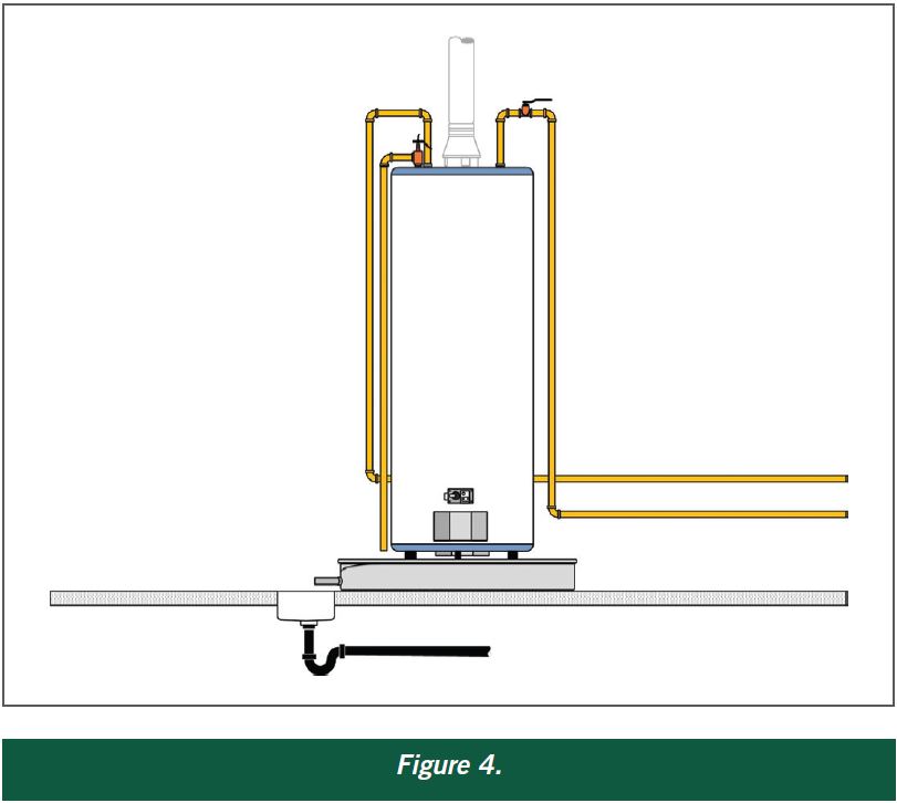
It is important to drain any rising discharge pipework.

. PSV Reaction force at the point of discharge for Gas Services in lbf F W366 KT K1MAP. My doubt is that set pressure of PSV is given as 1026 Kgcm2g. I have a rotary pump with casing design pressure at 160 Kgcm2g discharge piping design pressure at 130.
Design for the worst case scenario. PSV outlet pipe should be designed to avoid excessive backpressure erosional tendency and noise. PRV discharging steam to atmosphere shall have outlet piping in such a way that vapor clouds will not envelope any platform.
O The vent line should be sized such that back pressure is not placed on the drip pan elbow. Horizontal pipework should have a downward gradient of at least 1 in 100 away from the valve ensuring that any discharge will be self-draining. V flow coefficient for the relief valve C r rated valve capacity lbs.
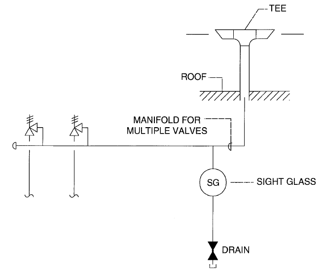
Thus in above example maximum set. The installation of a high pressure high-volume pressure relief valve must be carefully designed in order to ensure reliable operation and the safety of personnel when the valve operates and to prevent environmental damage from the discharge stream. Vent piping o The diameter of the vent pipe must be equal to or greater than the safety valve outlet.
PRV in liquid service and discharging to atmosphere shall do at a visible and safe place. Also rated discharge pressure is 922 Kgcm2a. I built-up backpressure should not exceed the overpressure of the PSV in case of conventional type PSV and approximately 50 of total backpressure superimposed plus built-up in case of balanced bellows type ii Mach No.
PRV discharging to closesd system shall be installed so that the discharge piping is free draining into the header. The ASME Boiler and Pressure Vessel Code and publications by many manufacturers caution the design engineer to consider back pressure in discharge piping when sizing and selecting pressure relief valves. The following is a summary of the ASME B313 rules.
30224 f states that the design conditions shall remain within. API Recommended Practice 520 5th Edition Part 2 7 and ANSI API Standard 521 5 provide guidance on the installation and design of the inlet and discharge piping for pressure safety valves. When evaluating an existing system discharging to the atmosphere the key design considerations that must be checked for this PSV application.
We are designing new pressure vessels with design pressure of 1200 kPag with PSVs set at 1200 kPag and flare discharge piping connects to an existing flare system. The valve consists of a valve inlet or nozzle mounted on the pressurized system a. PRESSURE RELIEF DEVICE INLET AND DISCHARGE PIPING GUIDE FOR ONTARIO BOILERS AND PRESSURE VESSELS REGULATION OREG22001 AND ONTARIO OPERATING ENGINEERS REGULATION OREG.
We are designing new pressure vessels with design pressure of 1200 kPag with PSVs set at 1200 kPag and flare discharge piping connects to an existing flare system. This applies to all PRD discharge piping that is interconnected with other PRDs through a common discharge header. It is recommended that discharge pipework should rise for steam and gas systems whereas for liquids it should fall.
This paper addresses manifolded discharge piping. PStatic pressure within the outlet at the point of discharge in psig. Design pressure can be considered in place of MAWP for this purpose as design pressure does not exceed MAWP.
The design of inlet and discharge piping must take into account the pressure to which the piping. The discharge piping serving a pressure relief valve temperature relief valve or combination valve shall. Pressure safety valve required discharge area in the case of steam.
Hence design should meet following criteria. Airmin kgs P 1 valve set pressure psig 11 atmospheric pressure P 1 valve set pressure barg11 1 bar When you know the adjusted system flow coefficient C v0 the adjusted flow C a through the relief valve assembly can be calculated using the following equation. O Minimize the length of the vent pipe.
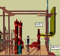
PSV Inlet and Discharge Piping Another area that requires close attention is the proper design of the inlet and discharge piping of the pressure safety valves. O The discharge outlet of. PSV is provided at the discharge piping to protect the pump and piping in case of inadvertent closure of discharge valve.
The PSV is more likely to chatter with a high pressure drop down a small discharge line than it is with the low pressure drop you will get with the large discharge line. Only general guidelines are given however because of widely varying installation requirements. The valve consists of a valve inlet or nozzle mounted on the pressurized system a.
Evaluation of Existing Systems. Cp and CvSpecific heat at the constant pressure and at constant volume respectively. K N 1 if P 1 10339 kPa abs.
The PSV discharge piping system should be designed so that the backpressure does not exceed an acceptable value for any pressure-relief device in the system. Additionally the PSV discharge piping design pressure and test pressure. The correction factor K N can be calculated the following way.
Fig-ure F2-1 shows the construction of a spring loaded pressure relief valve. It is not at all unusual for a PSV discharge line to be significantly larger then the discharge nozzle. Normally PSV discharge piping would have lower design pressure since its open pipe to flare ie pressure is limited to backpressure from hydraulic losses in the piping and flare system only.
This information paper details how to design pressure relief device PRD common discharge header piping following the requirements of CSA B51-14 except for Clauses 12227 and 12228 and ASME Section VIII Division I Appendix M. Vi While set pressure cannot exceed the maximum allowable working pressure MAWP for single operating PSV it can exceed the MAWP for one or more PSVs in case of multiple operating PSVs eg. The high flow rates in the small pipe would lead to pressures higher than the atmosphere right at the discharge of the pipe.
This is a general guide intended to assist Designers Installers and Inspectors in determining when pressure relief device discharge piping must terminate inside. PSV set pressure should be accordance with Section VIII Division 1 with exception stated below. K N 002764P 1 -1000 003324P 1 -1061 if 10339 P 1 22057 kPa.
Atmospheric Termination Of Relief Valve Discharge Piping

Water Worker Amtrol Steel Water Heater Expansion Tank 15 H X 11 5 W Water Heater Water Heater Expansion Tank Water Heater Expansion Tanks
Piping Engineering How To Design Safety Valve Line Youtube

Relief Valves For Centrifugal Pumps According To Nfpa 20 Fire Protection Specialists

Modeling Relief Valve Pressure Safety Valve Thrust Force Blog

The Dos And Don Ts Of Isolating Pressure Relief Valves Valve Magazine
Open Discharge Psv What Is Piping

Your Opinion On This Sticky Subject Psv Closed System Intergraph Cadworx Analysis
0 comments
Post a Comment